Introduction
Earthing switches shall be provided in the disconnectors based on the requirement and for earthing purposes. The earthing switches will be closed when the disconnector is in off condition and vice versa for earthing the induced current and voltages on the busbar when the circuit is open condition / maintenance purpose. This also will take care of the short circuit current when the main disconnector is in open condition.
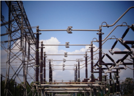
The disconnectors are normally horizontal upright mounted. In case to bring the bus from the gantry and to meet busbar configuration, either under hung type or vertical type shall be used.
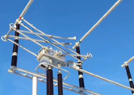
Double break disconnector also known as center post roatating disconnector provides isolation by way of circuit disconnections at the two ends (incoming & outgoing ends)
DOUBLE BREAK DISCONNECTOR COMPRISES
The Rotating hamper assembly consists of a tubular section of Aluminium/Copper of adequate cross section clamped at the centre point. It rotates 110° degrees for the closing / opening of the disconnector. The size of the Aluminium/Copper tube and its thickness is selected based on the continuous and short time current carrying capacity of the required disconnector. Silver plated copper contacts are fixed on to this rotating tube blade at either ends.
S&S Double Break Disconnectors are of a special design, have a turn and twist feature. In this design, the disconnector blade first moves in the horizontal plane and after touching a stopper on the fixed contact, the tubular blade itself rotates giving a twisting motion. Only during this twisting movement, the contacts mounted on the moving blade actually make contact with the fingers on the fixed contact assembly. This rotating motion of the blades ensures that adequate contact pressure is built up between the fixed and moving contacts for carrying the rated currents. This design also has a further advantage that during the closing operation of the disconnector, the actual current carrying surfaces do not come into the contact till the twisting motion occurs, thereby ensuring that there will not be any damage to the surfaces of the contacts during the closing of disconnector. The contacts are of self-wiping type and the contact surfaces get cleaned while closing and opening of Disconnector. This type of contact arrangement is called the pressure relieving reverse loop type.
An actuator housing assembly hold the Aluminium/ Copper tube. The turn and twist mechanism is clamped to the moving aluminium/copper blades. The actuator housing flange is then mounted on to top flange of the centre insulator of each pole.
Each pole of the Disconnector consists of two fixed contact assemblies. The fixed contact assembly consists of a housing onto which the Silver plated Copper contact fingers are mounted. Each contact finger is independently provided with a spring compression to ensure that the required contact pressure is maintained.
The fixed contact assembly also consists of a terminal pad. The terminal connector is fixed onto this terminal pad on four/six holes provided thereon.
The Double Break Disconnector consists of three stacks of support insulators per pole or 9 stacks per 3 pole disconnector. Out of the three insulators per pole, the outer two insulators are stationary and centre insulator rotates through 118 degrees for closing / opening of the Disconnector. Due to this reason, this type of Disconnector is also referred to as the Double Break Centre post Rotating type disconnector.
The fixed contact assemblies are mounted on top of the outer stacks of insulator which are stationary and the turn and twist mechanism along with the rotating hamper assembly is mounted on the centre stack of insulator.
The function of the outer stack of insulator is to keep the fixed contacts rigid, provide the necessary creepage distance and the insulation between the live parts and ground. The function of the centre stack of the insulator is to rotate though 118° degrees, provide the necessary creepage distance and the insulation between live parts and ground. Insulator corona rings are provided for 420kV / 245kV Disconnectors.
Disconnector base is made of mild steel welded assembly. The base consists of three flanges, two at either ends or one at the centre for mounting the support insulators. These flanges are provided with the necessary holes at the required pitch circle diameter to match with the holes provided on the insulator base flange. The two end flanges are welded on to the base of the disconnector adaptors. The centre flange is welded to the bearing shaft. The bearing shaft is assembled with two bearings, in a bearing housing. These bearings are seated one on top and another on bottom of the bearing housing base assembly and thus ensure smooth and free movement of the Centre rotating post of the disconnectors. Bearing caps are provided to ensure that water and dust do not enter the bearings. Provision is made on the base for mounting the mechanical constructional interlock between disconnector and earth switch wherever required.
The base is provided with mounting arrangements at four / eight points for fixing the disconnector base the supporting structure.
Earthing pad / earthing studs are provided at two points at the extreme ends of the base for connecting to the customers sub station earthing systems.
Inter Phase coupling pipes are provided to couple the three phases of the Disconnector and operate all the three phases from a common operating mechanism in the case of mechanically ganged three pole Disconnectors. These are not required in the case of single pole Disconnectors where each pole is operated by its own operating mechanism. The coupling pipes are linked to one base flange on each phase of the three pole disconnector. These are despatched loose and are to be assembled at site. Provision is available to do minor adjustments in length of the coupling pipe to suit site conditions.
Wherever specified, support structure of tubular types for 420kV disconnector and lattice type for 245kV and below disconnectors with necessary foundation bolts can be supplied. Plates are welded on to this tubular support structure fabricated out of welded sheet steel for 420kV Disconnectors for mounting the operating mechanism boxes. The height of this support structure can be varied to accommodate the bus height as required by the purchaser’s layout and system.
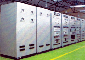
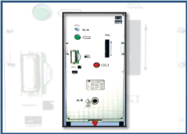
The operating mechanisms of the disconnectors / earth switches are mounted on to the structure on plates provided, being bolted with the angles that are provided on the mechanism box. Motor Operating mechanism or manual Operating Mechanisms can be supplied as per customer requirement.
The following interlocks are provided for the Horizontal Double break disconnectors.
- A mechanical constructional interlock between the disconnector and earth switch has been provided to ensure that the Earth Switch can be closed only when the Disconnector is in the open position and vice versa.
- An electrical(bolt coil type) key type interlock has been provided in each motor operating mechanism for interlocking between manual and motor operation of Disconnector / Earth switch. This ensures that the motor circuit is cut off when the manual operation is under progress.
- Optionally electro-mechanical (Castel key type) interlock can also be provided.
- In some cases, only electrical bolt coils are provided as interlocks solely controlled by electrical circuits.
- Based on customer needs either Electro-mechanical or Electrical interlocks will be provided.
- Electrical contact is provided in the Electrical circuit of the Motor Operating Mechanism for the Purchaser to wire in the external interlocks if any to ensure that the Disconnectors/ Earth switch can be operated only if all the interlocking conditions are satisfied. Note:
- Horizontal Double Break Disconnector can be supplied by us either without Earth switch, with Single Earth switch or with Double Earth switch.
- Double Break Disconnectors are normally offered for Horizontal, normal level, upright mounting. But on request these can be offered for other types of mounting like series, vertical; higher level, underhung, tandem etc.,
- Horizontal Double Break disconnectors / Earth switches supplied by us are generally Mechanically Ganged for operation of all three poles from a common operating mechanism cabinet. However we can supply 420kV double Break Disconnectors with the three poles being operated by 3 separate mechanisms, which are electrically ganged to operate together, if so desired by the purchaser
- Horizontal double break disconnectors can be
supplied with the following ratings (included in our present range of manufacture).
Maximum Voltage 420 kV Maximum current 4000 Amps Maximum short time withstand current 50kA r.m.s for 1 Sec with 125kA peak (or) 40kA r.m.s for 3 sec with 100kA peak. - Unless specifically stated in our offer, all cabling and wiring external to our operating Mechanism cabinets are excluded from the scope of our offer.